
Drawings Flow of Info
THE DRAWING SET CONSISTS OF MULTIPLE PARTS AND SYSTEMS THAT WORK TOGETHER TO DESCRIBE THE BUILDING.
THE DRAWING SET INCLUDES
Drawings w/Annotations
Schedules
General Notes
Key notes
Specifications
Assemblies
Details
Sheet Notes
All parts must work together in a coordinated whole to fully describe the work to be accomplished by the contractor.
DRAWINGS FLOW OF INFORMATION
THIS IS A TYPICAL SET FLOW DIAGRAM. THE STRATEGIES LAID OUT IN THIS SECTION ARE A BASE TO WORK FROM. THERE WILL ALWAYS BE EXCEPTIONS TO THE RULES.
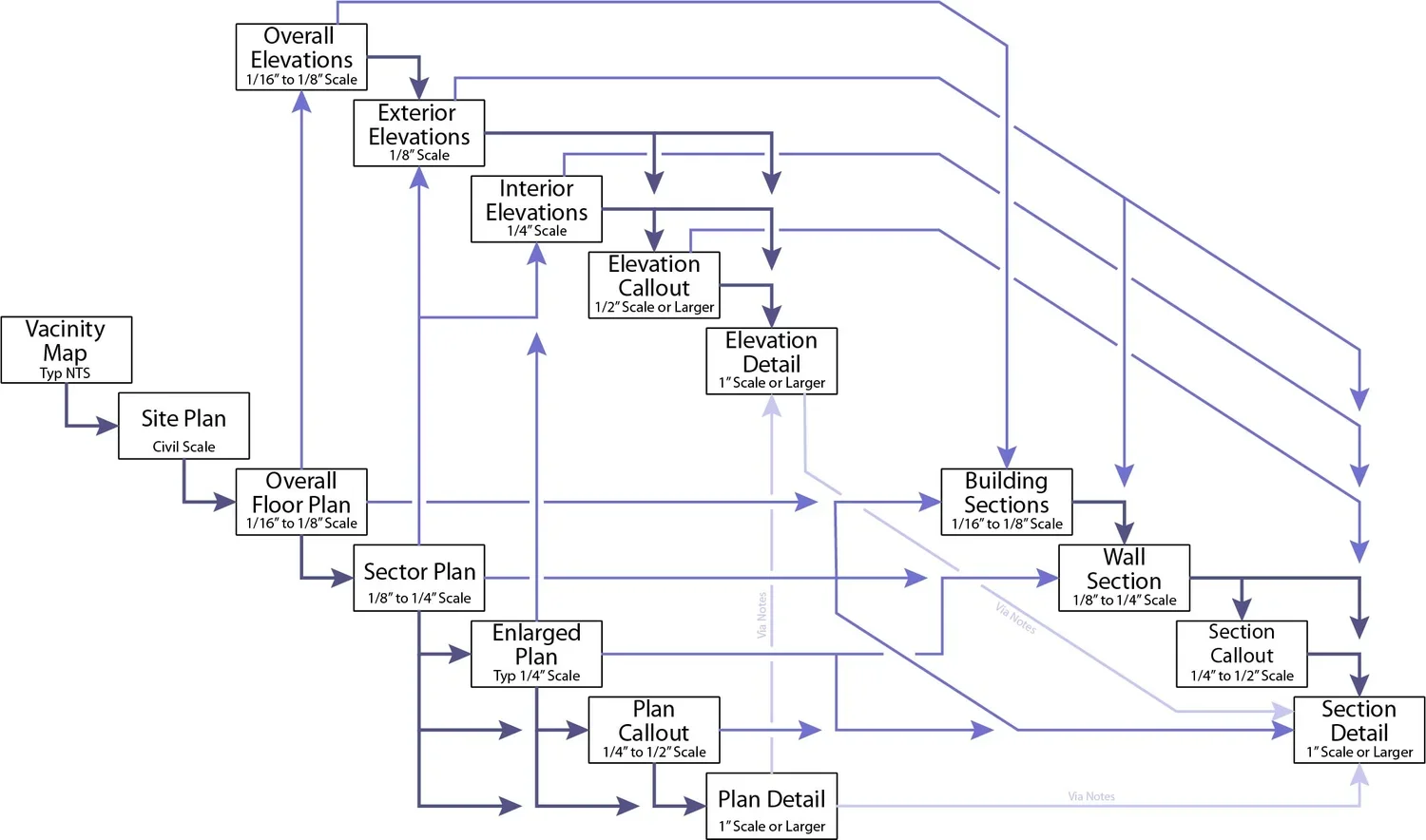
The drawings really begin with the Vicinity Map which orients a person to the Site Plan which in turn orients a person to the Floor Plans.
Floor plans is where the majority of the information in the set begins and everything tends to work its way toward the details. As such the floor plans are most relied upon by the contractors (especially the ones in the field, swinging the hammers) and they sometimes neglect to look through the rest of the set unless directed to by the plans. This means that all information needs to tie back to the floor plan for better communication.
ANNOTATION PASS THROUGH
Annotation information (dimensions, tags, keynotes, text notes, int elevation symbols, further call-outs, etc.) within a call-out (Plan, Elevation, Section, Detail or otherwise) will be omitted from the view on which the call-out is placed and passed through to the larger scale plan. In this way annotation is layered in the reverse direction of the diagram. Areas within call-outs should be relatively free of annotation. Only information such as room tags should remain for overall orientation purposes. Door tags may also want to remain to allow for "one stop shopping" on that particular item.
Details on the other hand may generically reference back to the plan (via a generic assembly tag on the detail) where the assembly is called out rather than calling out a specific assembly type in the detail. This allows the detail to reference a number of areas despite a change in assemblies.
AVOID DUPLICATION OF INFORMATION
Duplication of information should be limited within the set and only used for specific purposes. This is true as well of duplication of paths to other views. One path is all that is required, however there are instances when two or more paths may be desired for increased clarity. Back in the day this was done to reduce redundancy and therefore minimizing mistakes between views as an update to one call-out or tag would require a manual update to all duplications if you even knew where they were. With BIM this is no longer an issue, but management of the project and work load still make this good practice. Put in just enough information to make the documents clear.